
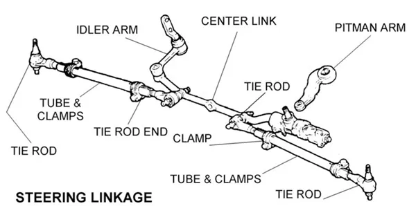
A center link inspection requires more than matching steering play, vibration, pulling, or noise to a suspected part. Those symptoms can come from several steering, suspension, wheel, or tire conditions. If you replace the center link without testing the full linkage, you may leave the actual fault untouched and create unnecessary repair costs.
To inspect a center link, review the reported symptoms, examine the link and connection points for visible deterioration, and check for abnormal movement under the load specified by the vehicle manufacturer. Compare both ends and inspect the pitman arm, idler arm, tie-rod ends, fasteners, and mounting points before deciding whether replacement is justified.

Our experience comes from center-link production, assembly, final inspection, and documented return communication. That gives us product-condition expertise, but it does not replace vehicle-level diagnosis. You should always verify lifting methods, movement limits, fastener procedures, and safety requirements against current OEM service information.
What Should You Check Before a Center Link Inspection?
A driver may describe loose steering, vibration, pulling, clunking, or delayed steering response. These complaints matter, but they do not identify the defective component. If you begin with a conclusion instead of evidence, the inspection can quickly become a parts-replacement exercise rather than a structured diagnosis.
Start by documenting when the symptom occurs and checking basic wheel, tire, steering, and suspension conditions. Then identify the steering-linkage design and locate the center link, pitman arm, idler arm, tie-rod ends, mounting points, and fasteners. Use the correct OEM inspection procedure before applying force or raising the vehicle.

Treat symptoms as inspection prompts
Steering symptoms can help you decide where and how to inspect, but they cannot prove that the center link has failed.
For example:
- Steering play may involve linkage joints, a worn idler arm, steering gear movement, mounting-point looseness, or another connection.
- Vehicle pulling can relate to alignment, tire pressure, tire construction, brake drag, road crown, or suspension geometry.
- Vibration may begin at a wheel, tire, hub, driveline component, or loose steering connection.
- Clunking or knocking can come from several steering and suspension joints.
- Uneven tire wear may indicate alignment or suspension problems rather than a defective center link.
You should record the operating conditions associated with the complaint. Note whether it happens when the vehicle is stationary, during low-speed steering, over uneven roads, while braking, or at highway speed. This information helps a qualified technician reproduce the concern safely.
Identify the steering system before testing
Not every vehicle uses the same linkage arrangement. The center link, sometimes called a relay rod or drag-link-related component in certain catalogs, transfers steering movement through connected parts. Its test method depends on the vehicle design and joint construction.
Before beginning, confirm:
- The vehicle application and steering configuration.
- The correct service information for that model and year.
- The specified lifting and support points.
- Whether the inspection requires the wheels to be loaded, unloaded, or placed on turn plates.
- Whether an assistant must move the steering wheel during observation.
- Any manufacturer-defined movement, torque, or replacement criteria.
Never rely on a universal play measurement or torque value. A limit that applies to one design may be inappropriate for another. If the correct procedure is unavailable, further evaluation by a qualified steering and suspension professional is safer than guessing.
How Do You Visually Inspect a Center Link?
A visual inspection can reveal deformation, cracking, boot damage, corrosion, contamination, loose fasteners, and contact marks. However, a center link can look normal and still contain internal wear or abnormal movement.1 Visual findings should support the diagnosis, not become the entire diagnosis.
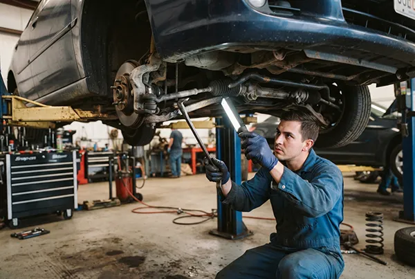
Clean enough dirt from the component to expose its body, joints, boots, fasteners, and connection points. Use adequate lighting and compare both ends where applicable. Record any abnormality before disturbing fasteners or disassembling the linkage, since removal can erase useful evidence about movement or installation condition.

Examine the center-link body
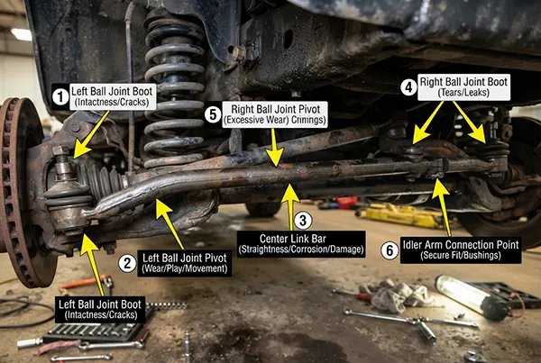
Inspect the complete body rather than only the joint areas. You should look for:
- Bending, twisting, or other deformation
- Cracks around transitions, forged sections, or machined areas
- Heavy impact marks or fresh metal contact
- Severe corrosion, pitting, or material loss
- Evidence of interference with nearby components
- Damaged threads or distorted mounting surfaces
- Previous heating, welding, grinding, or unauthorized modification
A bent center link may change steering geometry2, but you should not judge straightness from memory or compare it with a part for a different vehicle. Some links have intentional curves and offsets. Compare the component with verified drawings, service information, or a confirmed correct replacement.
In our manufacturing work, dimensional control starts with the drawing and the specified datum points. The same logic applies during inspection: appearance alone is not a reliable dimensional standard.
Inspect boots, seals, and joint areas
A damaged dust boot can allow water, grit, and road contaminants to enter a joint.3 Check for splits, punctures, hardening, displacement, missing retaining rings, and leakage around the sealing area.
Boot damage is important evidence, but it does not automatically prove that the joint has exceeded its service limit.4 You still need to evaluate movement and follow the manufacturer’s criteria. Conversely, an intact boot does not guarantee that the internal joint is sound.
You should also examine:
- Tapered-stud seating
- Nuts, locking devices, and cotter pins where fitted
- Signs that a stud has moved inside its mounting hole
- Rust trails or polished surfaces that suggest movement
- Damaged grease fittings on serviceable designs
- Contamination around the joint
- Incorrect or missing hardware
Do not tighten a loose-looking fastener to an assumed value. First determine why it is loose and whether the stud, taper, threads, mounting hole, or connected part has been damaged. Use only the application-specific tightening method and specification.
How Do You Check a Center Link for Abnormal Movement?
Hidden play is often more important than surface appearance. The challenge is separating intended joint articulation from unwanted clearance. If you apply force in the wrong direction or test the linkage under the wrong load, normal movement may appear defective, while genuine wear may remain hidden.
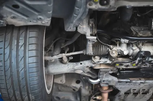
Check center-link movement using the OEM procedure and an appropriate load condition. Observe each joint and connection while controlled steering or hand force is applied. Compare the two ends where their designs are equivalent, and watch for independent movement, delay, knocking, or displacement at connected mounting points.

Load the linkage correctly
A steering joint is designed to articulate through a defined angle. Smooth angular movement is not the same as free play.5 Abnormal clearance generally appears as movement between surfaces that should remain securely engaged, but the acceptable amount and approved test method vary by application.
Depending on the vehicle, the manufacturer may require:
- The vehicle to remain at normal ride height
- The front wheels to be raised or supported in a specified way
- An assistant to move the steering wheel through a limited range
- A lever or measuring tool placed at a defined location
- A dial indicator or another approved measuring device
- Inspection with the engine running or stopped
- A comparison against a model-specific service limit
You should not improvise by using excessive leverage. Excessive force can move compliant parts, damage a boot, create misleading movement, or destabilize an improperly supported vehicle.
> Follow the vehicle manufacturer’s lifting, support, steering-lock, and movement-measurement procedures. Never work beneath a vehicle supported only by a jack.6
Distinguish articulation from looseness
Watch the stud, housing, center-link body, and connected arm at the same time. You are looking for the point where movement begins and whether one component moves without immediately transferring motion to the next.
Useful observations include:
- Does the stud articulate smoothly, or does it shift inside the housing?
- Does the complete joint move because the mounting point is loose?
- Does the pitman arm begin moving before the center link responds?
- Does the center link move while the idler-arm mounting point shifts?
- Is movement similar at both comparable ends, or is one side clearly different?
- Can you hear or feel a knock at the same moment that visible displacement occurs?
Comparison is valuable, but it is not a substitute for specifications. Both sides could be worn, or their joint designs could differ. Your observation should be measured against verified service criteria whenever the manufacturer provides them.
If no visible defect appears but the symptom remains, do not assume that the part is serviceable. The next step may require measurement, disassembly under an approved procedure, alignment checks, or diagnosis by a qualified professional.
Why Must You Inspect the Center Link With Adjacent Parts?
The center link works as part of a connected steering system. Movement at the idler arm, pitman arm, tie-rod ends, steering gear, mounting brackets, or fasteners can appear to originate in the link itself. Inspecting only one component can therefore produce a false failure conclusion.
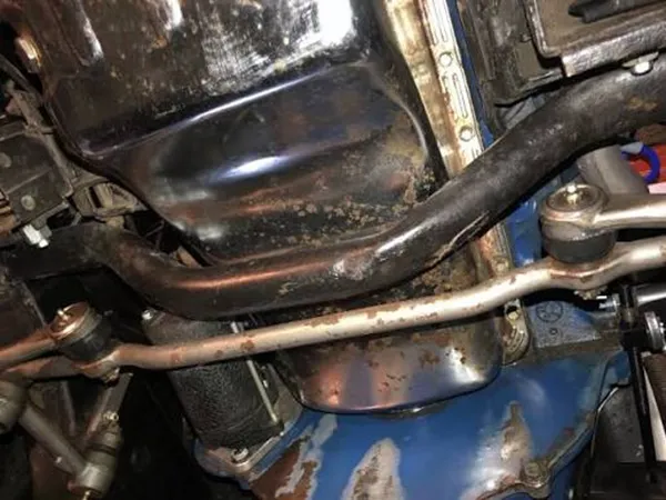
Observe the entire steering linkage while the test load is applied. Follow movement from the steering input through the pitman arm and center link to the idler arm and tie-rod connections. Record the exact location of abnormal movement before approving removal or replacement.

Follow the movement path
A useful inspection sequence is:
- Steering gear and mounting: Check for observable housing or mounting movement according to the service procedure.
- Pitman-arm connection: Observe the arm, shaft connection, and center-link joint.
- Center-link body and joints: Look for delay, free movement, deformation, and joint displacement.
- Idler arm and bracket: Check whether the arm or its mounting point rises, drops, or shifts abnormally.
- Tie-rod ends and adjusters: Inspect inner and outer joints, sleeves, clamps, threads, and fasteners.
- Related wheel and suspension points: Consider other components when the symptom suggests a broader problem.
A loose bracket can imitate joint wear because the entire connection moves under steering load. Likewise, wear at a tie-rod end may create steering play even when the center link remains within specification.
Document evidence before replacement
Your inspection record should identify what was observed, where it occurred, and how it was tested. Useful documentation includes:
| Record item | What to capture |
|---|---|
| Reported symptom | Driver’s description and operating conditions |
| Vehicle information | Model, year, configuration, and mileage |
| Test condition | Loaded or unloaded, engine status, and support method |
| Visual findings | Boot condition, corrosion, deformation, and fasteners |
| Movement findings | Exact joint or mounting point where movement occurred |
| Measurement | Tool used and OEM limit, if applicable |
| Adjacent components | Pitman arm, idler arm, tie rods, and mounting points |
| Evidence | Clear photographs, video, and inspection notes |
| Decision | Replacement, adjustment, monitoring, or further diagnosis |
Our documented complaint and return communications have shown that symptom-only claims are difficult to evaluate. A returned component may arrive with a reported steering concern, yet the available record may not include the loaded movement result, connection-point condition, or inspection of adjacent parts. Without those facts, a vehicle-level cause cannot be confirmed from the returned part alone.
That limitation matters. Factory inspection can evaluate material condition, dimensions, assembly features, and the returned product’s observable state. It cannot reconstruct every installation condition or diagnose the complete vehicle without reliable field evidence. A good record protects the repair decision and makes any later technical review more useful.
Frequently Asked Questions
Can a center link look normal but still be worn?
Yes. An intact surface and undamaged dust boot do not rule out internal clearance or wear. You should check movement under the load and method specified by the vehicle manufacturer. You should also compare connected joints and mounting points before deciding that the center link is serviceable.
Does loose steering prove that the center link has failed?
No. Loose steering can result from several steering-linkage joints, an idler arm, steering gear movement, mounting-point looseness, or other conditions. Treat steering play as a reason to inspect the complete system. Confirm the location of abnormal movement before replacing any component.
Should you replace a center link when its dust boot is torn?
A torn boot is evidence of lost protection and possible contamination, but the repair decision depends on the component design, joint condition, replacement policy, and OEM guidance. Inspect for corrosion, contamination, and abnormal movement. Do not assume that boot appearance alone establishes the full condition of the joint.
Can you use the same play limit for every center link?
No. Joint designs, steering systems, testing positions, and service limits vary between vehicle applications. Universal clearance and torque values can produce incorrect decisions. You should use current OEM service information for the exact vehicle and seek qualified professional evaluation when the proper specification is unavailable.
Is an alignment required after center-link replacement?
Alignment requirements depend on the vehicle design and the work performed. Steering-linkage replacement can affect steering geometry or reveal existing alignment issues.7 Follow the manufacturer’s repair procedure, verify steering-wheel position and linkage installation, and have the alignment checked or adjusted when the service information requires it.
Conclusion
A reliable center link inspection combines symptom documentation, visible-condition checks, loaded movement testing, and comparison with the complete steering linkage. Steering play, noise, pulling, or vibration should start an inspection, not decide its outcome. You should verify every test method, wear limit, and fastener specification against OEM information. If you need center links manufactured to verified drawings, samples, or aftermarket specifications, contact GDST Auto Parts to discuss OEM/ODM production, quality documentation, testing, packaging, and application coverage.
"8+ Signs: How to Tell If a Ball Joint is Bad (DIY Guide)", https://bigblue.atlantisuniversity.edu/how-to-tell-if-a-ball-joint-is-bad/. Because the bearing and contact surfaces of a housed steering joint are internal, wear-related clearance may be detected through a prescribed movement test even when the exterior body and dust boot show no obvious damage. Evidence role: mechanism; source type: education. Supports: Technical training material should explain that wear within a housed steering joint may create clearance without obvious exterior deformation or boot damage.. Scope note: This mechanism establishes that concealed wear is possible; it does not show that a visually normal center link is necessarily worn. ↩
"Cross Steering Linkage Design and Turning Radius Analysis", https://www.academia.edu/31344443/Cross_Steering_Linkage_Design_and_Turning_Radius_Analysis. Steering-geometry references indicate that deformation of a linkage member can alter the location and effective motion of its connection points, potentially changing toe or other steering relationships. Evidence role: mechanism; source type: education. Supports: A steering-system reference should explain that deformation of a linkage member can change linkage position, toe relationships, or steering kinematics.. Scope note: The amount and direction of any geometry change depend on the specific linkage design and the location and magnitude of the deformation. ↩
"Md. Code Regs. 11.14.09.04 - Steering, Alignment, and ...", https://www.law.cornell.edu/regulations/maryland/COMAR-11-14-09-04. Tribological studies of lubricated joints show that seal damage can permit water and abrasive particles to enter the contact region, where contamination may degrade lubrication and promote corrosion or wear. Evidence role: mechanism; source type: paper. Supports: Research on sealed or lubricated joints should show that loss of sealing can admit water and abrasive particles to contact surfaces.. Scope note: General tribology evidence explains the contamination mechanism but does not prove that contamination has entered or damaged a particular center-link joint. ↩
".04 Steering, Alignment, and Suspension.", https://regs.maryland.gov/us/md/exec/comar/11.14.09.04. Inspection guidance commonly records a damaged steering-joint boot as a defect or contamination risk while assessing joint looseness and security under separate criteria. Evidence role: general_support; source type: government. Supports: An inspection standard should distinguish protective-boot condition from separate criteria for joint looseness, security, or wear.. Scope note: Some jurisdictions or manufacturers may require replacement solely because of boot damage, so the applicable service policy must still be consulted. ↩
"8+ Fixes: How to Tighten Steering Wheel Play (DIY)", https://bigblue.atlantisuniversity.edu/how-to-tighten-steering-wheel-play/. In a ball-and-socket steering joint, articulation is the intended angular rotation needed to accommodate linkage motion, whereas free play refers to unintended relative displacement arising from clearance or loss of secure engagement. Evidence role: definition; source type: education. Supports: Technical literature should distinguish intended angular rotation of a ball-and-socket steering joint from translational clearance associated with wear.. Scope note: The permissible direction and magnitude of movement depend on joint construction and the manufacturer’s test method. ↩
"Citation 1276530.015/01001 | Occupational Safety and ...", https://www.osha.gov/ords/imis/generalsearch.citation_detail?id. Occupational-safety guidance warns that lifting jacks are not substitutes for stable vehicle supports and directs workers to secure a raised vehicle with appropriately rated stands or equivalent equipment before entering the space beneath it. Evidence role: expert_consensus; source type: government. Supports: Government safety guidance should require a raised vehicle to be secured with rated supports before anyone works underneath it.. ↩
"MKIII Golf/Jetta Inner and Outer Tie rod DIY.", https://faculty.ccp.edu/faculty/dreed/campingart/jettatech/tierods/tierods.htm. Automotive service references advise verifying wheel alignment after steering-linkage work when the repair changes or disturbs linkage length, toe adjustment, or steering-wheel centering. Evidence role: general_support; source type: education. Supports: Automotive service literature should explain that work affecting steering-linkage length or position can change toe or steering-wheel centering and may require alignment verification.. Scope note: A center-link replacement does not necessarily change alignment on every design; the need for measurement or adjustment depends on the vehicle and the work performed. ↩