
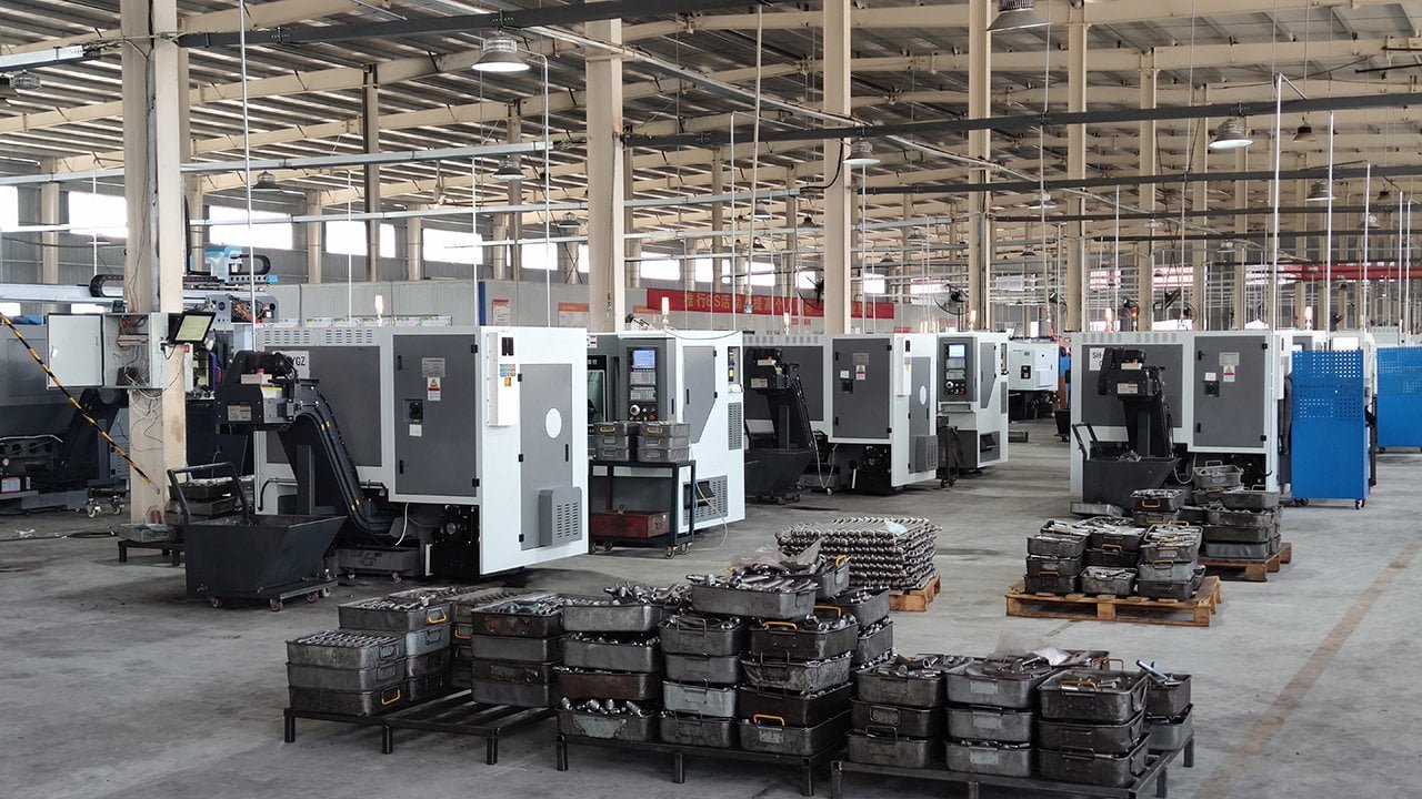
Most buyers compare sway bar links by price and dimensions. But the failures that generate warranty returns and customer complaints have almost nothing to do with either. They come from decisions made on the production floor that never appear on a spec sheet.
Sway bar links are manufactured through a sequence of forging or casting, ball stud assembly, bushing vulcanization, surface treatment, and final mechanical testing. Each step has specific process controls that determine whether the part holds up in the field or fails early. Knowing what those controls are — and how to ask about them — is how buyers separate reliable suppliers from low-price risks.
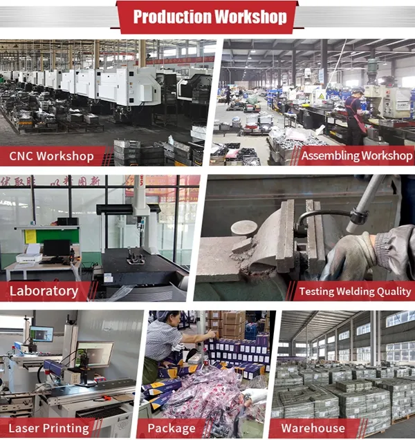
I've been involved in sway bar link production for more than 20 years. In that time, I've seen the same failure patterns repeat — not because the parts looked wrong, but because a specific step in manufacturing was skipped or poorly controlled. This article walks through each step. For every step, I'll tell you what we monitor in our own production, and what question you should ask any supplier you're evaluating.
Does the Body Start as a Forging or a Casting?
This is the first question most buyers never think to ask. The link body looks the same whether it was forged or cast. The surface finish looks similar. The dimensions can be identical. But the internal material structure is completely different — and that difference determines how the part behaves under repeated stress.
Forging forces steel into a die under high pressure, aligning the grain structure of the metal along the shape of the part. Casting pours molten metal into a mold. Cast steel can contain internal voids, inconsistent grain orientation, and lower fatigue resistance. Under cyclic load — which is exactly what a sway bar link experiences — cast links are more likely to crack or deform over time.
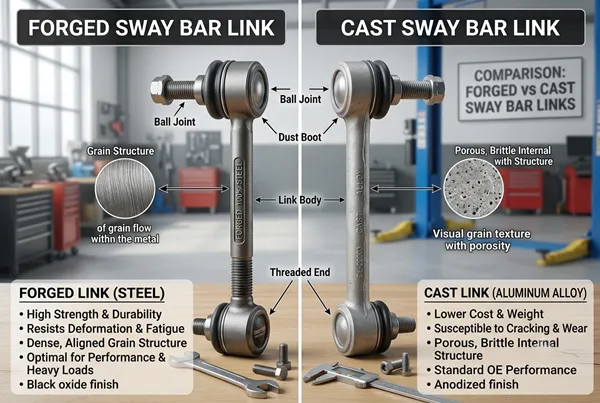
I want to be clear about why this matters in practical terms. A sway bar link flexes and compresses every time the suspension moves. In urban driving, that can mean thousands of cycles per day. The part doesn't fail from a single overload — it fails from accumulated fatigue.1 Forged steel resists that accumulation better than cast steel because the grain structure is denser and more uniform.
The problem for you are that you cannot detect this from a photo, a sample inspection, or even a standard dimensional check. You need to ask the supplier directly: is this part forged or cast? If they hesitate, or if they describe a process that sounds like sand casting or die casting for a structural link body, that is a red flag.
In our process at GDST, link bodies are produced through drop forging. We use steel sourced from suppliers including Baosteel, Shagang, and Yuanli — all of which provide material inspection reports per batch. We also conduct random chemical composition tests in-house to verify the incoming material meets our spec before it enters production. This isn't just documentation for audit purposes. It's how we catch material substitution early, before it becomes a field failure.
| Factor | Forging | Casting |
|---|---|---|
| Grain structure | Aligned, dense | Random, may contain voids |
| Fatigue resistance | High | Lower |
| Visual difference | None visible externally | None visible externally |
| Failure mode under cyclic load | Gradual deformation | Cracking, fracture |
| How to verify | Ask directly, request process documentation | Same |
If a supplier cannot tell you their forming method, or cannot show you process documentation, assume the worst and move on.
How Does Ball Stud Assembly Affect Real-World Performance?
Buyers almost always focus on fitment dimensions — thread size, stud length, mounting hole spacing. Those matter. But they are not what causes early NVH complaints or premature wear. The actual failure driver at the ball stud level is angular play outside of spec during assembly.
A ball stud that is assembled with too much angular clearance will move beyond its designed range under load. This generates noise, accelerates wear on the socket and bearing seat, and eventually causes the stud to pull out of the housing. The acceptable articulation range varies by vehicle application, but the principle is the same: assembly tolerance must be controlled to a tight band, and verified after assembly — not estimated.
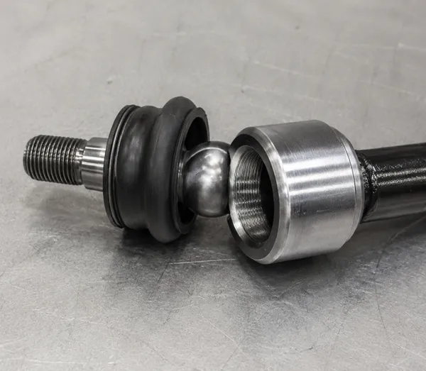
Let me explain what "controlled assembly" means in our production environment, because this term is often used loosely by suppliers.
At GDST, ball stud assembly involves controlling both the press-fit force applied during installation and the post-assembly articulation angle. The press-fit force determines how firmly the stud is seated in the housing. Too little force and the stud will have excessive play. Too much force and the bearing seat deforms, restricting movement and accelerating wear from the opposite direction.
After assembly, we verify the articulation angle — the range of motion the stud can move through — against the specification for that particular application. We also check starting torque, which is the resistance the stud offers at the beginning of movement. Both of these values tell us whether the assembly is within spec.
The question to ask any supplier: what is your press-fit force tolerance range, and how do you verify articulation angle after assembly? A supplier doing only dimensional inspection — checking thread length and stud diameter — is not controlling the quality variables that cause field failures. They're checking the variables that are easy to measure, not the ones that matter most.
| Assembly Variable | What It Controls | How It's Verified |
|---|---|---|
| Press-fit force | Stud seating firmness | Measured during press operation |
| Articulation angle | Range of movement under load | Post-assembly angle test |
| Starting torque | Resistance at movement initiation | Torque testing |
| Angular play | Excess movement causing NVH | Post-assembly functional check |
What Makes a Bushing Vulcanization Process Reliable or Not?
The rubber bushings on a sway bar link are not just cushions. They absorb vibration, maintain alignment under dynamic load, and protect the ball joint housing from direct metal contact. When they fail — which usually means hardening, cracking, or losing damping function — the noise and handling complaints come quickly.
Rubber bushing quality in sway bar links is primarily determined by the vulcanization process: the combination of temperature, pressure, and cure time that bonds rubber to metal and sets the rubber's final physical properties. A bushing that was under-cured feels acceptable at room temperature during inspection but hardens prematurely under ozone exposure, UV light, or temperature cycling in the field.2
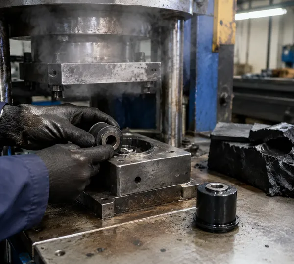
Most buyers inspect bushings visually and by feel during sample review. That tells you very little. A slightly under-cured bushing and a properly cured bushing feel almost identical at room temperature, fresh from production. The difference appears six months later, in a market where temperature swings are wide or road salt is used in winter.
In our process, vulcanization temperature and cure time are set and monitored per material specification for each bushing compound. We use ozone resistance testing to verify that the rubber maintains its properties under accelerated aging conditions. This test exposes the bushing to elevated ozone concentrations over a defined period and checks for surface cracking. Surface cracking under ozone exposure is an early indicator of premature field hardening.
The question to ask: do you conduct ozone resistance testing on bushings, and what is your minimum acceptable result? A supplier who has never run this test — or who doesn't know what it measures — is not controlling bushing longevity. They are shipping parts that passed a visual check and nothing more.
| Vulcanization Variable | Effect if Out of Spec | How GDST Controls It |
|---|---|---|
| Temperature | Under-cure → premature hardening | Monitored per compound spec |
| Cure time | Short time → incomplete cross-linking | Set by material specification |
| Rubber compound | Affects ozone/UV resistance | Verified by ozone resistance testing |
| Metal bond integrity | Delamination under dynamic load | Visual and pull test post-cure |
Can You Judge Surface Treatment Quality by Looking at It?
No. This is one of the most common mistakes I see buyers make. A bright, uniform zinc coating looks the same whether it will protect against corrosion for 72 hours or 500 hours under salt spray conditions.3 The coating appearance tells you nothing reliable about its durability.
Surface treatment quality on sway bar links is measured by salt spray testing: a controlled test where parts are exposed to a salt fog environment for a defined number of hours. The test tells you how long the coating resists rust formation in humid or coastal conditions. A part sold into tropical, coastal, or winter-salt markets without adequate salt spray performance will begin rusting within months of installation.
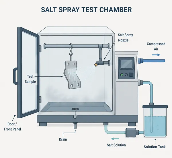
Let me explain what the test actually measures, because the number of hours means nothing without knowing the pass/fail criteria. Salt spray testing puts parts in a sealed chamber with a continuous mist of salt solution at a defined concentration and temperature.4 At the end of the test period — 72 hours, 120 hours, 240 hours, or more depending on the spec — parts are inspected for rust formation. The pass/fail criteria define where rust is and is not acceptable (e.g., no red rust on base metal; white rust on coating surface may be acceptable up to a defined coverage percentage).
What this means practically: a supplier who says "we use zinc plating" without specifying coating thickness, test hours, and pass/fail criteria is giving you a meaningless answer. Zinc plating at 5 microns behaves very differently from zinc plating at 12 microns.5 The question to ask: what is your zinc coating thickness specification, how many hours does your salt spray test run, and what is your pass/fail criterion?
For markets with high humidity, coastal conditions, or road salt use, I'd treat anything below 120 hours as insufficient for a premium aftermarket product. For standard dry-climate applications, 72 hours may be adequate — but the supplier should still be able to tell you the number and what it means.
| Surface Treatment Variable | What to Ask | Red Flag Answer |
|---|---|---|
| Coating type | Zinc plating, e-coat, or other? | "We use standard coating" |
| Coating thickness | Minimum micron spec? | No specified minimum |
| Salt spray test hours | How many hours? | "We do salt spray testing" (no number) |
| Pass/fail criteria | What counts as failure? | "No rust" (too vague) |
What Do Pull-Out Force and Fatigue Testing Actually Verify?
These are the two tests that determine whether a sway bar link is qualified for use — not just dimensionally correct, but structurally sound for its intended load and cycle requirements. A supplier who cannot give you specific numbers for both tests is doing inspection, not qualification.
Pull-out force testing measures the force required to separate the ball stud from its housing under axial load. It verifies that the assembly will hold together under worst-case stress. Fatigue testing cycles the part through repeated load applications that simulate real driving conditions, verifying that the part does not crack, deform, or lose function before a defined minimum cycle count.
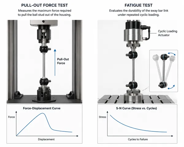
These two tests answer different questions. Pull-out force tells you about a single worst-case event — a hard impact, a pothole, an off-road shock load. Fatigue testing tells you about cumulative performance over the part's service life. Both are necessary. A part can pass pull-out force at a high value but still fail fatigue testing if the material or heat treatment is wrong.
In our production at GDST, both tests are part of our product qualification protocol. We set internal minimum values for pull-out force per product application, and fatigue testing is run to a defined cycle count before a new product enters mass production. I'm not going to state those numbers here as if they're universal industry benchmarks — they vary by application and vehicle type. But I will tell you what a credible supplier answer looks like: a specific pull-out force value (in Newtons or kilonewtons) for a specific application, and a specific fatigue cycle count with the load conditions used during the test.
If a supplier tells you they do "standard quality testing" without being able to specify the test parameters or the minimum acceptable values, they are doing dimensional inspection and calling it quality control. That's not the same thing.
The questions to bring to your next supplier evaluation:
- What is your minimum pull-out force spec for this application, and how is it measured?
- What cycle count does your fatigue test run to, and what load conditions are applied?
- Can you share a test report from your most recent production batch?
| Test | What It Measures | What a Good Answer Looks Like |
|---|---|---|
| Pull-out force | Resistance to stud separation under axial load | Specific value in N or kN for the application |
| Fatigue testing | Part integrity under repeated load cycles | Specific cycle count + load conditions used |
| Torque testing | Articulation resistance within spec | Measured value vs. acceptable range |
| High/low temperature | Function retention across temperature range | Test range and pass/fail criteria stated |
Conclusion
Sway bar link quality comes down to five controllable steps: forging method, ball stud assembly tolerance, bushing vulcanization, surface treatment, and mechanical testing. Buyers who know which questions to ask can screen suppliers on process, not just price.
"Fatigue (material) - Wikipedia", https://en.wikipedia.org/wiki/Fatigue_(material). Mechanical engineering principles establish that components subjected to repeated cyclic loading typically fail through progressive fatigue crack propagation rather than single overload events, particularly when operating loads remain below yield strength. Evidence role: mechanism; source type: education. Supports: the predominance of fatigue failure over single-event failure in cyclically loaded automotive components. Scope note: General fatigue failure mechanism; actual failure modes in service depend on load magnitude, material properties, and presence of stress concentrations or manufacturing defects ↩
"Estimation of Synthetic Rubber Lifespan Based on Ozone ... - PMC", https://pmc.ncbi.nlm.nih.gov/articles/PMC11944956/. Polymer science research demonstrates that incomplete vulcanization results in lower crosslink density, which reduces resistance to oxidative degradation from ozone, UV radiation, and thermal cycling, though these effects may not be apparent during initial room-temperature inspection. Evidence role: mechanism; source type: research. Supports: the relationship between vulcanization completeness and rubber resistance to environmental degradation. Scope note: General rubber chemistry principles; specific degradation rates depend on rubber compound formulation, cure conditions, and environmental exposure severity ↩
"[PDF] Onset of failure in corrosion protective barrier coatings", https://www.waru.edu/sites/default/files/Migrated/CopDocuments/Onset%20of%20failure%20in%20corrosion%20protective%20barrier%20coatings.pdf. Corrosion engineering literature establishes that coating appearance provides limited information about protective performance, as corrosion resistance depends primarily on coating thickness, composition, and microstructure rather than visual characteristics. Evidence role: general_support; source type: education. Supports: the limitation of visual inspection for assessing protective coating performance. Scope note: General coating inspection principles; some visual defects (porosity, contamination) can indicate performance issues, but uniform appearance does not guarantee adequate protection ↩
"Salt spray test - Wikipedia", https://en.wikipedia.org/wiki/Salt_spray_test. Standardized salt spray testing methods, such as ASTM B117, specify exposure of test specimens to atomized sodium chloride solution in a controlled chamber at defined temperature and concentration to evaluate corrosion resistance. Evidence role: definition; source type: institution. Supports: the standardized procedure for salt spray corrosion testing. ↩
"The Effect of Zinc Bath Formulation on the Corrosion Resistance of ...", https://pmc.ncbi.nlm.nih.gov/articles/PMC11923840/. Corrosion protection studies demonstrate that zinc coating performance increases with thickness, with typical automotive specifications ranging from 5-15 microns depending on service environment, as thicker coatings provide longer sacrificial protection before substrate exposure. Evidence role: general_support; source type: research. Supports: the relationship between zinc coating thickness and corrosion protection performance. Scope note: Performance also depends on coating uniformity, substrate preparation, and post-treatment; thickness alone does not guarantee protection without proper application quality ↩