
Automotive Control Arms Manufacturer for OEM & Aftermarket Supply
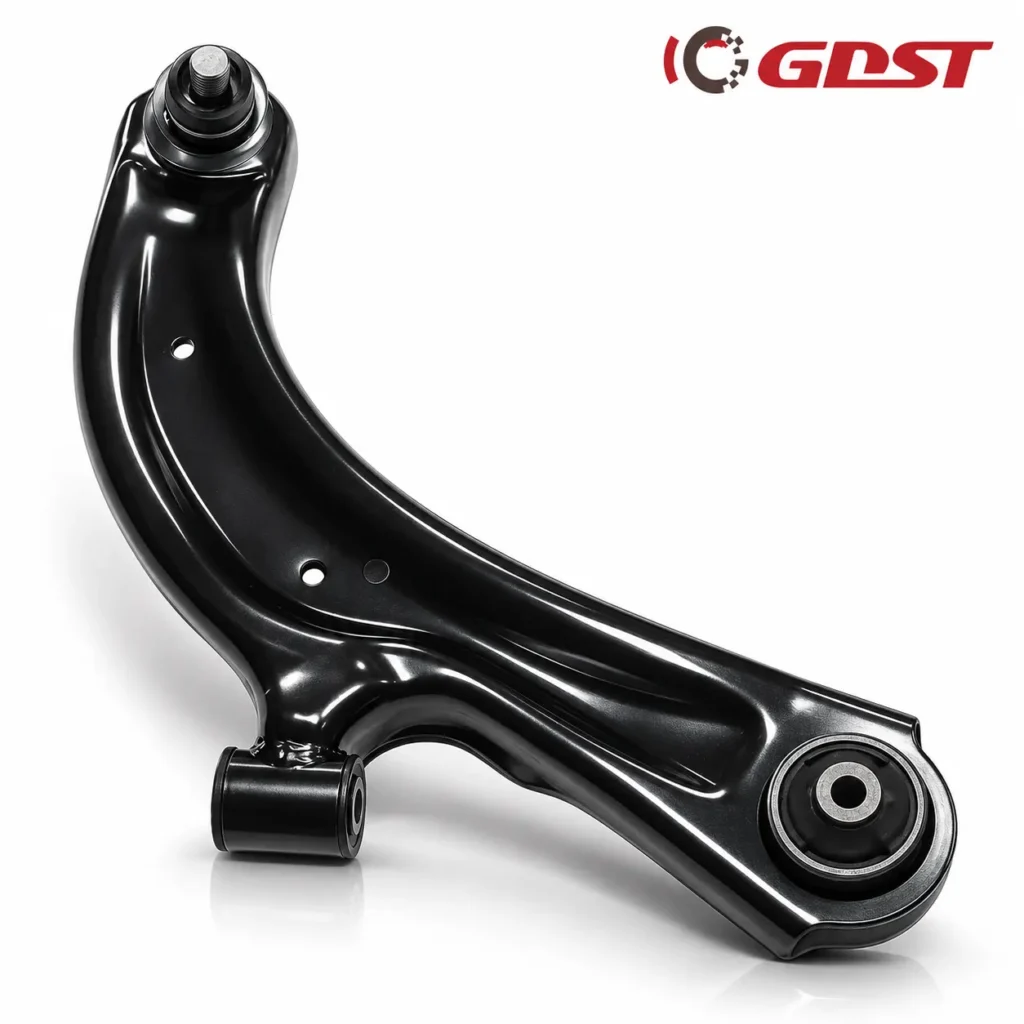
- MOQ
- 50PCS
- Price
- $10-$30
- Warranty
- 1 Year From Receipt of Goods
- Delivery Time
- 45-55 Days
- Customization
-
- Customized Logo
- Customized Packaging
- ODM/Sample Development
ISO9001 Certified
Fast Delivery
OEM/ODM
Upper & Lower Control Arms | Front & Rear Suspension Arms | OE Reference Matching
Wuhu GDST Auto Parts Co.,Ltd manufactures aftermarket automotive control arms for automotive parts distributors, wholesalers, importers, and private-label brands. Our product range covers upper control arms, lower control arms, front and rear suspension arms, and complete control arm assemblies for selected passenger cars, SUVs, and light commercial vehicles.
With product-specific dimensional inspection, assembly verification, and manufacturing support, we help aftermarket businesses source replacement suspension components according to their OE references and technical requirements.
From standard replacement control arms to customized product development and private-label packaging, GDST supports long-term automotive aftermarket sourcing projects.
| Car Brand | OEM NO. |
| NISSAN | 545400-3DN0A |
| MITSUBISHI | MB912077 |
| MAZDA | GJ6A-34-300 |
| TOYOTA | 48068-59035 |
| TOYOTA | 48605-35120 |
| SUZUKI | 45200-84000 |
| DAIHATSU | 48068-87515 |
| DAIHATSU | 48068-87705 |
| HYUNDAI | 54410-38000 |
| KIA | 54501-3S100 |
Download GDST Control Arms Catalog
What Is a Control Arm on a Car?
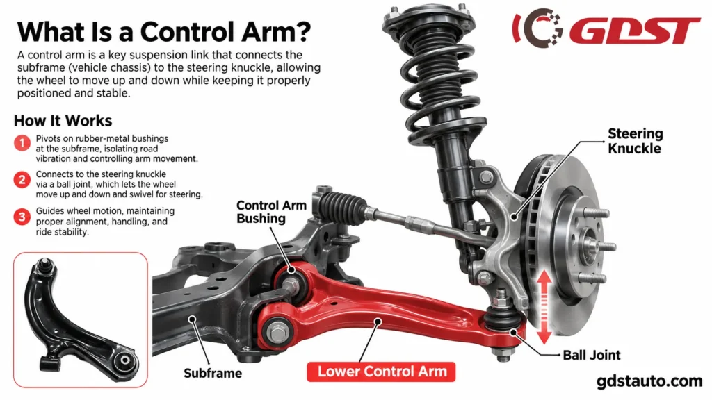
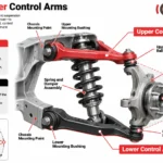
A control arm is a structural component of a vehicle’s suspension system that connects the chassis or subframe to the steering knuckle or wheel carrier. It allows the wheel to move vertically as the suspension responds to road conditions while helping maintain the designed wheel alignment geometry.
Also known as a suspension arm or A-arm in certain designs, the control arm plays an important role in vehicle handling, steering stability, and suspension performance.
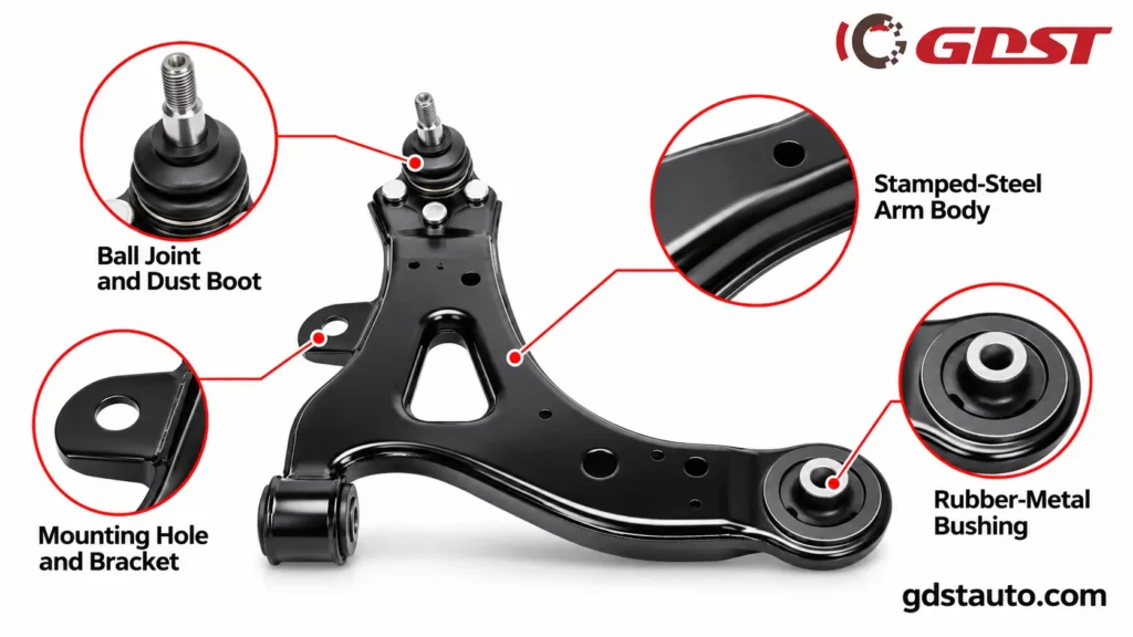
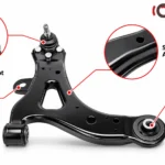
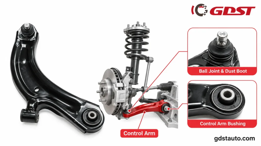
A typical control arm assembly consists of a metal arm body, mounting points, rubber or polyurethane bushings, and, depending on the design, an integrated or separately replaceable ball joint.
The inner mounting points connect the arm to the vehicle frame or subframe, while the outer connection attaches to the steering knuckle or wheel carrier. These joints allow controlled suspension movement while maintaining the wheel’s intended position.
For automotive aftermarket buyers, understanding the control arm structure is important when identifying replacement parts, confirming OE references, and selecting the correct assembly for a specific vehicle application.
Main Functions of an Automotive Control Arm
- Wheel Positioning: Helps maintain the designed position of the wheel assembly relative to the vehicle chassis.
- Suspension Movement: Allows controlled vertical movement as the suspension responds to road irregularities.
- Alignment Geometry: Contributes to maintaining the intended camber, caster, and other suspension geometry parameters, depending on the design.
- Structural Support: Provides a connection between the suspension assembly and the vehicle structure.
- Vibration Isolation: Works with suspension bushings to help reduce the transmission of road vibration and noise.
Understanding these functions helps buyers identify the correct control arm configuration and replacement requirements.
Where Is the Control Arm Located in a Vehicle?
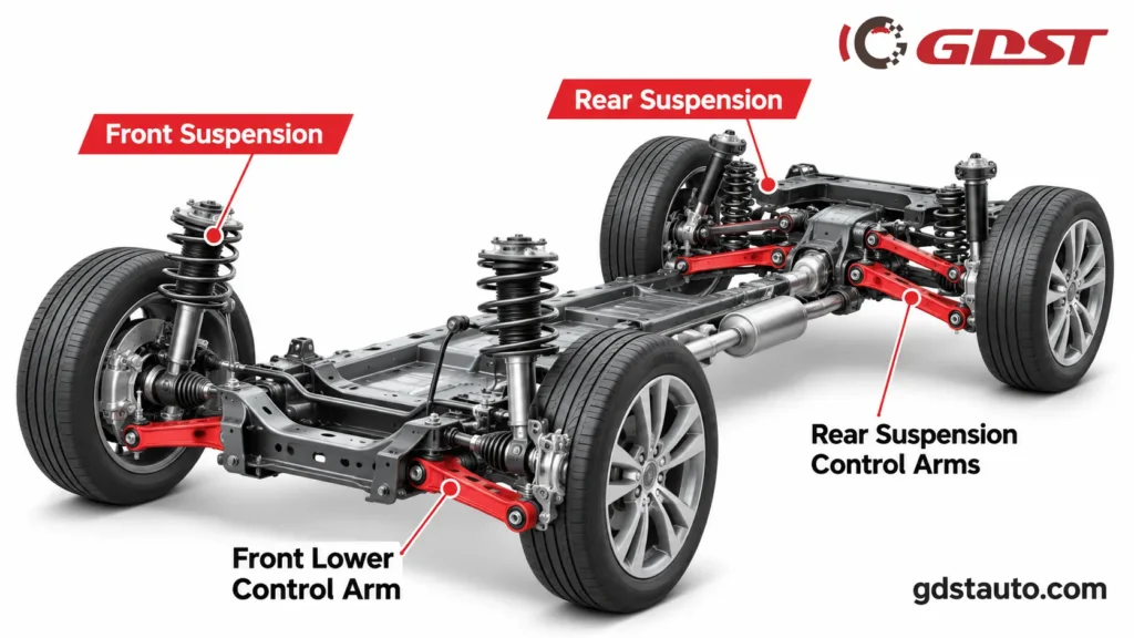
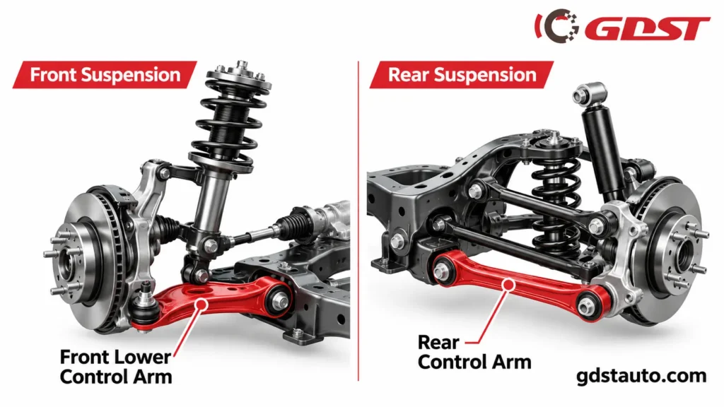
Control arms are located between the vehicle’s chassis or subframe and its wheel assemblies. They are typically installed within the front or rear suspension system, although their number, position, and configuration depend on the vehicle’s suspension design.
A front lower control arm is generally positioned below the steering knuckle, connecting the lower section of the wheel carrier to the vehicle’s subframe. In a double-wishbone suspension, an upper control arm is installed above it to provide an additional suspension locating point.
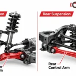
At the rear, control arms and related suspension links are used in independent and multi-link suspension systems to control wheel movement and maintain the designed suspension geometry.
Common Control Arm Positions
- Front Left Lower Control Arm
- Front Right Lower Control Arm
- Front Left Upper Control Arm
- Front Right Upper Control Arm
- Rear Left Control Arm
- Rear Right Control Arm
- Rear Upper Control Arm
- Rear Lower Control Arm
Not every vehicle uses all these configurations. For example, many MacPherson strut front suspensions use a lower control arm without a conventional upper control arm.
For accurate replacement or wholesale sourcing, the installation position must be confirmed using the vehicle application and OE reference number rather than relying on the general appearance of the part.
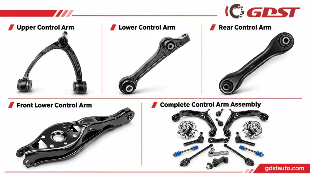
Types of Automotive Control Arms We Manufacture
GDST supplies aftermarket automotive control arms for selected passenger cars, SUVs, and light commercial vehicle applications.
Our product selection covers different suspension positions, structural designs, and assembly configurations to support the sourcing requirements of global automotive parts distributors and wholesalers.
Upper Control Arms
Upper control arms connect the upper section of the wheel carrier or steering knuckle to the vehicle’s chassis or suspension structure.
They help maintain suspension geometry, particularly camber and caster relationships, throughout suspension movement.
Upper control arms are commonly used in double-wishbone suspension systems and selected independent rear suspension designs.
GDST provides upper control arm solutions for compatible vehicle applications, with product identification based on OE references and technical specifications.
Lower Control Arms
Lower control arms connect the lower section of the steering knuckle or wheel carrier to the subframe or chassis.
They generally carry a significant share of suspension loading and help control wheel movement during acceleration, braking, and cornering.
Lower control arms are widely used in MacPherson strut and double-wishbone suspension systems.
GDST supplies lower control arms in different shapes and configurations according to the applicable vehicle design.
Front Lower Control Arms
Front lower control arms are important components of the front suspension system. They help maintain the position of the front wheels while allowing controlled vertical suspension movement.
Depending on the vehicle application, they may be designed with one or multiple mounting bushings and an integrated or separate ball joint.
For distributors sourcing car front lower control arms, GDST supports product identification and compatibility confirmation through OE numbers, vehicle information, and sample references.
Rear Control Arms
Rear control arms are used in independent rear suspension and multi-link suspension systems to manage rear wheel positioning and movement.
Unlike conventional front lower control arms, rear suspension arms may have different geometries, mounting arrangements, and joint configurations depending on the vehicle platform.
GDST supplies rear suspension arm products for selected vehicle applications, supporting replacement demand across different aftermarket markets.
Complete Control Arm Assemblies
Complete control arm assemblies combine the main arm body with selected mounting components, such as bushings and ball joints, depending on the original vehicle design.
This configuration can simplify replacement and reduce the need for separate component sourcing.
Available assembly configurations should be confirmed according to the relevant OE reference and product specification.
Control Arm Product Type Comparison
| Product Type | Installation Position | Main Application | Key Identification |
| Upper Control Arm | Upper suspension | Double-wishbone and selected multi-link systems | Upper position and mounting geometry |
| Lower Control Arm | Lower suspension | MacPherson and double-wishbone systems | Lower position and joint configuration |
| Front Lower Control Arm | Front axle, lower position | Front suspension replacement | LH/RH and OE number |
| Rear Control Arm | Rear suspension | Independent and multi-link systems | Rear position and link configuration |
| Complete Control Arm Assembly | Vehicle-specific | Complete replacement | Assembly contents and OE reference |
Upper vs. Lower Control Arms: What Is the Difference?
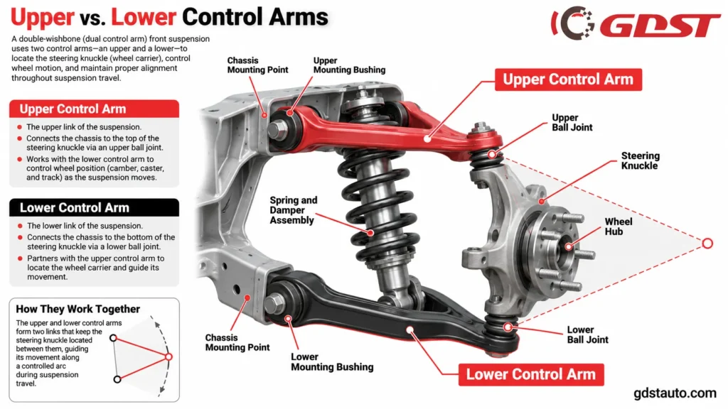
Upper and lower control arms work together in suspension systems designed with two control arms at each wheel. However, their positions, dimensions, load conditions, and suspension geometry functions are different.
The upper control arm connects the upper part of the wheel carrier to the chassis, while the lower control arm connects its lower section to the vehicle structure.
Lower control arms often handle a greater share of suspension loading, while upper control arms help define and maintain the upper suspension locating geometry. Their exact responsibilities vary according to suspension architecture.
| Comparison | Upper Control Arm | Lower Control Arm |
| Installation Position | Above the wheel carrier connection | Below the wheel carrier connection |
| Main Function | Controls upper suspension geometry | Supports and locates the lower suspension connection |
| Typical Shape | A-shaped, wishbone, or application-specific | A-shaped, L-shaped, or application-specific |
| Mounting | Bushings or application-specific joints | Bushings or application-specific joints |
| Ball Joint | Integrated or separately installed, depending on design | Integrated or separately installed, depending on design |
| Common Application | Double-wishbone and selected multi-link systems | MacPherson, double-wishbone, and selected multi-link systems |
Do All Cars Have Upper and Lower Control Arms?
No. The number of control arms depends on the suspension architecture.
A double-wishbone suspension normally uses both upper and lower control arms at each wheel.
A MacPherson strut suspension generally uses a lower control arm, while the strut assembly provides the upper suspension locating function.
Multi-link suspension systems use several separate links to control different aspects of wheel movement and alignment.
Therefore, buyers should verify the vehicle’s original suspension layout before selecting an upper or lower control arm.
Front vs. Rear Control Arms: Design and Application
Front and rear control arms serve similar fundamental purposes, but they are not interchangeable unless specifically designed for the same application.
Front control arms are commonly associated with steering geometry because the front wheels are responsible for directional control in most passenger vehicles.
Rear control arms are primarily used to locate and control the movement of the rear wheels. In multi-link rear suspension systems, several different arm types may work together to control lateral movement, longitudinal movement, camber, and toe.
| Comparison | Front Control Arms | Rear Control Arms |
| Main Location | Front suspension | Rear suspension |
| Main Function | Support wheel location and suspension movement while maintaining steering geometry | Control rear wheel location and suspension movement |
| Common Designs | Upper, lower, A-shaped, L-shaped | Upper, lower, lateral, trailing, and application-specific links |
| Steering Relationship | Associated with front wheel steering geometry | Usually not directly connected to the steering rack |
| Fitment Factors | LH/RH, front axle, upper/lower, OE number | Rear axle, link position, LH/RH, OE number |
For automotive parts distributors, identifying the correct front or rear suspension position is essential when preparing product catalogs and matching replacement control arms.
GDST supports product identification through OE numbers, samples, drawings, and vehicle application details.
Control Arm Materials, Components and Specifications
Material selection and component quality directly affect control arm strength, weight, corrosion resistance, and durability.
Depending on the original vehicle design and performance requirements, automotive control arms may use different steel or aluminum material specifications and manufacturing methods.
Material grade, thickness, forming process, and structural requirements must be confirmed against the individual product drawing rather than assuming one material is suitable for every control arm.
Control Arm Material Selection
| Material / Construction | Main Characteristics | Typical Considerations |
| Stamped Steel | Suitable for forming complex suspension arm geometries and volume production | Material grade, thickness, forming quality, and corrosion protection |
| Forged Steel | Can provide high structural strength when properly engineered | Forging quality, heat treatment, and machining requirements |
| Cast Iron | Provides stiffness and load-bearing capability in selected designs | Weight and application-specific structural requirements |
| Cast Aluminum | Offers weight reduction and corrosion resistance | Casting quality and fatigue performance |
| Forged Aluminum | Provides high strength-to-weight potential in suitable designs | Forging process, heat treatment, and machining precision |
The actual material options available for each GDST product must be confirmed through the corresponding product specification and material documentation.
Main Components of an Automotive Control Arm
Control Arm Body
The main structural component connects the suspension mounting points. Its geometry and material requirements are determined by the vehicle’s original suspension design.
Control Arm Bushings
Bushings are flexible mounting components installed at the chassis or subframe connection points. They allow controlled pivoting and help isolate noise and vibration.
Ball Joint
The ball joint provides articulation between the control arm and steering knuckle or wheel carrier in applications using this joint configuration.
Dust Boot
The dust boot protects the ball joint’s internal interface from external contaminants and helps retain the specified lubricant where applicable.
Mounting Brackets and Fixing Points
These structural interfaces secure the control arm to the chassis or subframe and must follow the original mounting geometry.
Control Arm Technical Specification Reference
The following table identifies the key technical information that buyers should confirm when sourcing control arms.
| Specification | Description | Confirmation Method |
| Product Type | Upper, lower, front, or rear control arm | Product drawing / OE reference |
| Vehicle Application | Make, model, year, and engine version | Vehicle catalog / OE lookup |
| Installation Position | Front or rear, upper or lower | OE specification |
| Side | Left-hand or right-hand | OE reference/drawing |
| Main Material | Product-specific steel or aluminum specification | Material documentation |
| Arm Construction | Stamped, forged, cast, or application-specific | Product drawing |
| Bushing Configuration | Quantity, dimensions, and material specification | Technical drawing/sample |
| Ball Joint Configuration | Integrated, bolt-on, press-in, or not included | Assembly specification |
| Surface Treatment | E-coating, powder coating, or other specified finish | Coating specification |
| Dimensions | Length, width, mounting distance, and hole position | Approved drawing |
| Packaging | Neutral, bulk, or customized private-label packaging | Customer requirement |
GDST evaluates control arm specifications based on OE references, physical samples, and technical drawings to support product matching and development.
Model-Specific Control Arm Specifications and Inspection Records
Automotive control arms are designed according to specific vehicle applications, mounting geometries, and suspension requirements. Therefore, dimensional specifications and assembly configurations vary between part numbers.
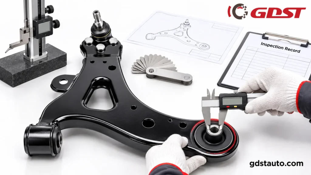
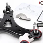
At GDST, control arm inspection is carried out according to product-specific technical requirements.
Our outgoing inspection records cover critical dimensions, threaded connections, bushing interfaces, dust boot assembly, surface finish, and other applicable quality checkpoints.
The following examples illustrate the types of specifications and inspection results documented for selected control arm references.
Representative Control Arm Inspection Data
| Inspection Reference | Thread Specification | Key Dimensional Requirements | Recorded Inspection Results |
| Reference A | M16 × 1.5 | Height: 300 ± 1.5 mm; Overall length: 303 ± 2 mm | Height: 299–301.2 mm; Overall length: 302.3–305 mm |
| Reference B | M16 × 1.5 (Ball joint thread) | Small bushing ID: Ø16.5 ± 0.2 mm; Small bushing OD: Ø73 ± 0.2 mm; Large bushing ID: Ø16.5 ± 0.2 mm | Recorded as OK against specified requirements |
| Reference C | M12 × 1.25 (Ball joint thread) | Bushing center distance: 295 ± 1.5 mm; Small bushing ID: Ø12.2 ± 0.2 mm; Small bushing OD: Ø64 ± 0.2 mm | Center distance: 294.8–296.5 mm; Small bushing ID: Ø12.0–12.3 mm; Small bushing OD: Ø63.9–64.1 mm |
| Reference D | M16 × 1.5 | Height: 276 ± 5 mm; Overall length: 303 ± 2 mm | Height: 275–280 mm; Overall length: 302.3–305 mm |
Additional Recorded Bushing Dimensions
For selected control arm references, outgoing inspection records also include the following bushing dimensions:
| Inspection Reference | Inspection Item | Technical Requirement | Recorded Result |
| Reference B | Large bushing ID | Ø16.5 ± 0.2 mm | OK |
| Reference B | Distance between the outer sides of the two bushings | 448 ± 3 mm | OK |
| Reference C | Large bushing ID | Ø17 ± 0.2 mm | Ø16.8–17.2 mm |
| Reference C | Large bushing OD | Ø62.4 ± 0.3 mm | Ø62.2–62.5 mm |
Additional Inspection Items
Depending on the product reference, our inspection records also cover:
- Visual condition: checking for dents, rust, and other visible defects.
- Dust boot assembly: verifying correct installation and checking for visible damage.
- Surface treatment: checking the specified black electrophoretic coating.
- Thread verification: checking specified thread dimensions.
- Taper inspection: using taper gauges where applicable.
- Bushing dimensions: checking inner diameter, outer diameter, and mounting distances.
- Assembly torque: recording torque measurements for applicable references.
- Packaging inspection: checking labels, shipping marks, cartons, and pallet arrangements according to customer requirements.
These examples are taken from actual outgoing inspection records. The reviewed batches were recorded as meeting their specified requirements and approved for release.
Important: The listed values are reference-specific, not universal specifications for all GDST control arms. Final dimensions and tolerances are subject to the applicable product drawing and approved specifications.
For detailed specifications, please provide your OE number or product reference to our technical team.
How to Identify the Right Control Arm for Your Vehicle
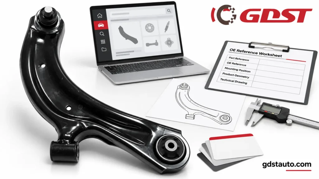
Selecting the correct control arm requires more than identifying whether the part is an upper or lower arm. Different vehicle generations and suspension configurations may use different mounting dimensions, joint designs, and installation positions.
For aftermarket distributors and wholesale buyers, accurate OE cross-reference matching is essential to reduce incorrect orders and fitment-related returns.
GDST recommends confirming the following information before placing an order.
Vehicle Make, Model, and Year
Provide the vehicle manufacturer, model, production year, and relevant engine or drivetrain configuration.
The same vehicle model may use different control arm designs across different production generations.
OE Number or Reference Number
The original equipment reference number is one of the most useful ways to identify a replacement control arm.
Providing the OE number allows the product team to check the corresponding product configuration and cross-reference information.
Installation Position
Confirm whether the required component is:
- Front or rear.
- Upper or lower.
- Left-hand or right-hand.
- Front axle or rear axle.
- Individual suspension arm or complete assembly.
Product Photos or Physical Samples
When an OE number is unavailable, buyers can provide product photographs, dimensional drawings, or physical samples.
These references help evaluate the arm shape, mounting points, bushing configuration, ball joint position, and overall dimensions.
Product Identification Checklist
| Information | Example | Importance |
| Vehicle Make | Toyota | Required |
| Vehicle Model | Corolla | Required |
| Production Year | 2020 | Required |
| Installation Position | Front Lower | Required |
| Side | Left / Right | Required |
| OE Number | Original reference number | Highly recommended |
| Product Photo | Front and rear views | Helpful |
| Sample / Drawing | Physical sample or 2D/3D drawing | Helpful for development |
| Order Quantity | Estimated annual or initial demand | Required for quotation |
Accurate product identification helps both parties confirm technical compatibility, quotation details, and production requirements before order confirmation.
Control Arm Manufacturing and Quality Control
Reliable control arms require consistent material quality, accurate forming, secure joint connections, and effective corrosion protection.
GDST follows product-specific manufacturing and inspection requirements designed to maintain dimensional consistency and assembly quality across aftermarket orders.
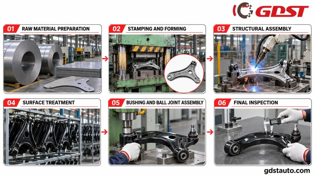
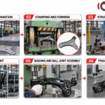
Control Arm Manufacturing Process
Raw Material Preparation
Steel or other specified materials are selected according to the product design and manufacturing requirements. Incoming materials are checked against the relevant specifications.
Precision Stamping or Forming
Metal components are formed using application-specific tooling to achieve the required geometry and mounting structure.
Cleaning and Deburring
Formed components are cleaned and processed to remove oil, contaminants, and unwanted edges before subsequent manufacturing operations.
Welding and Structural Assembly
Where required by the design, components are joined through controlled welding processes to achieve the specified structural configuration.
Surface Treatment
Appropriate surface protection is applied according to the product requirements. Black electrophoretic coating is specified in the outgoing inspection records of the four control arm references reviewed.
Bushing and Ball Joint Assembly
Bushings and ball joints are installed according to the specified mounting configuration and assembly requirements.
Dimensional and Functional Inspection
Critical dimensions, mounting positions, component installation, and appearance are checked against the approved specifications.
Final Inspection and Packaging
Finished products undergo outgoing inspection before being labeled, packed, and prepared for shipment.
Control Arm Quality Inspection and Testing
Consistent product quality requires more than visual inspection. Control arm specifications involve multiple dimensions, threaded connections, mounting interfaces, and assembled components.
Based on our documented outgoing inspection records, the following checkpoints are included where applicable.
Visual Inspection
Control arms are checked for visible dents, rust, surface damage, and other appearance defects before shipment.
Dust Boot Assembly Inspection
Dust boots are inspected to verify correct installation and check for visible cracks, damage, or improper assembly.
Surface Finish Inspection
Black electrophoretic coating is specified in the reviewed control arm inspection records. Surface appearance and treatment conformity are checked according to the applicable product requirements.
Thread and Taper Inspection
Thread specifications are verified according to the individual product reference. Taper dimensions are also checked using taper gauges for applicable control arm assemblies.
Bushing Dimensional Inspection
Bushing inner diameters, outer diameters, and mounting distances are measured according to the product drawing.
These dimensions are important for correct installation and suspension assembly compatibility.
Overall Dimensional Inspection
Selected product references include inspection of overall length, height, mounting hole diameter, and center distances.
Measurement methods recorded in our inspection documents include dial calipers and height gauges.
Torque Inspection
Torque measurements are recorded for applicable control arm references using a torque gauge. The inspection limits and measurement points depend on the relevant product specification.
Final Inspection and Packaging Verification
Finished products are checked against the applicable inspection requirements before shipment. Packaging checks include customer-specified labels, shipping marks, cartons, and pallet arrangements.
Documented Quality Inspection Capabilities
| Inspection Category | Inspection Equipment / Method | Documented Application |
| Appearance | Visual inspection | All four reviewed references |
| Dust Boot Assembly | Visual inspection | All four reviewed references |
| Surface Treatment | According to applicable product requirements | All four reviewed references |
| Thread | Thread specification verification | All four reviewed references |
| Taper | Taper gauge | Selected references |
| Bushing Dimensions | Dimensional measurement | Selected references |
| Mounting Geometry | Dimensional measurement/height gauge | Selected references |
| Overall Length and Height | Caliper/height gauge | Selected references |
| Torque | Torque gauge | Selected references |
| Packaging | Packaging inspection | All four reviewed references |
Each of the four reviewed outgoing inspection sheets records a conclusion that the inspected batch met its specified requirements and was approved for release.
Inspection items and acceptance criteria are defined according to the individual control arm reference rather than applying one universal specification to the entire product range.
Raw Material Selection and Traceability
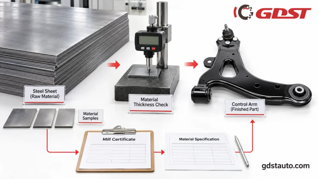
The quality and consistency of automotive control arms start with appropriate raw material selection.
Material grade, thickness, mechanical properties, and forming requirements must be matched to the original product design and approved technical specifications.
For applicable steel control arm programs, material documentation can be used to verify specified material characteristics and support production traceability.
Important material information includes:
- Steel grade and material specification.
- Material thickness and dimensions.
- Yield strength and tensile strength, where specified.
- Elongation and other relevant mechanical properties.
- Supplier material certificates.
- Production lot and material batch identification.
Material requirements vary between control arm designs. Therefore, material properties should always be evaluated against the corresponding product drawing and approved material specification.
For customers with specific material requirements, GDST can discuss the applicable material documentation and technical verification arrangements during product evaluation.
OEM, ODM and Private Label Control Arm Solutions
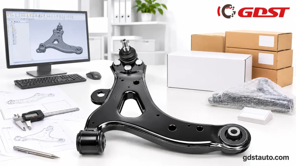
GDST supports automotive aftermarket businesses looking to expand their control arm product ranges, develop replacement parts, and establish their own automotive parts brands.
Our cooperation options can be arranged according to the customer’s technical requirements, order quantity, and packaging preferences.
OE Reference-Based Product Development
For customers looking to introduce new control arm references, GDST can evaluate available OE numbers, physical samples, and technical drawings.
The development process may include:
- Product structure evaluation.
- Sample measurement and comparison.
- Dimensional drawing review.
- Tooling and manufacturing feasibility.
- Prototype or sample confirmation.
- Pre-production approval.
Custom Logo and Private Label Packaging
Depending on the product and order requirements, GDST can support:
| Customization Option | Available Solution |
| Product Branding | Logo marking according to product feasibility |
| Product Label | Customized part number and brand label |
| Inner Packaging | Customized bags and protective packaging |
| Outer Carton | Private-label carton design |
| Product Identification | OE reference and customer part number |
| New Product Development | Drawing- or sample-based evaluation |
Customers can provide their existing packaging artwork or request assistance with packaging design according to the agreed specifications.
Bulk Wholesale Supply
GDST works with automotive parts importers, distributors, wholesalers, and aftermarket brands.
We support product assortment planning, multi-reference orders, packaging coordination, and export documentation to help customers manage their control arm sourcing programs.
Why Choose GDST as Your Control Arm Supplier?
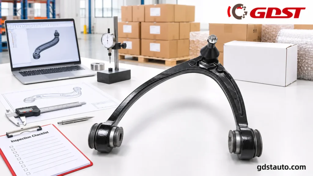
Choosing a control arm supplier requires evaluating more than the unit price. Product compatibility, manufacturing consistency, quality management, delivery planning, and after-sales support all influence long-term sourcing performance.
GDST provides automotive suspension and steering components for international aftermarket customers, with product development and export experience.
Wide Vehicle Application Coverage
Our control arm product range covers selected Japanese, Korean, American, and European vehicle applications.
We support product identification through OE numbers, samples, and vehicle information.
Manufacturing and Engineering Support
GDST provides manufacturing support for different control arm structures and product configurations, including application-specific stamped and formed designs.
Product-Specific Quality Inspection
Our documented outgoing inspection records include dimensional measurements, thread verification, bushing inspection, dust boot assembly checks, surface finish inspection, and other applicable checkpoints.
Technical Documentation
Selected control arm references have corresponding inspection records. Technical specifications and available product documentation can be discussed during the quotation and product confirmation process.
Flexible Private Label Cooperation
We support customized product identification, labels, and packaging to help distributors and aftermarket brands develop their own product ranges.
Export-Oriented Supply
With experience serving international automotive aftermarket customers, GDST supports order coordination, export documentation, packaging arrangements, and shipment preparation.
Long-Term Aftermarket Cooperation
Our objective is to help customers establish a stable supply relationship through consistent product specifications, clear communication, and ongoing sourcing support.
Frequently Asked Questions About Automotive Control Arms
What does a control arm do on a car?
A control arm connects the vehicle’s chassis or subframe to the steering knuckle or wheel carrier. It allows controlled suspension movement while helping maintain wheel alignment geometry and vehicle stability.
Where is the lower control arm located on a car?
The lower control arm is generally located below the steering knuckle or wheel carrier. It connects the lower suspension mounting point to the vehicle’s chassis or subframe. Its exact location and configuration depend on the vehicle’s suspension design.
What is the difference between an upper and a lower control arm?
The upper control arm connects the upper suspension locating point to the chassis, while the lower control arm connects the lower locating point. In double-wishbone suspension systems, they work together to control wheel movement and suspension geometry. Lower arms generally carry a greater share of suspension loading.
Do all cars have upper and lower control arms?
No. Vehicles with double-wishbone suspension generally have both upper and lower control arms. Many vehicles using MacPherson strut suspension have only a lower control arm, with the strut assembly providing the upper locating function.
What is the difference between front and rear control arms?
Front control arms are part of the front suspension and contribute to maintaining steering and wheel alignment geometry. Rear control arms are used to locate and control rear wheel movement, particularly in independent and multi-link suspension systems. Their shapes, mounting points, and configurations vary by vehicle application.
What are the common symptoms of a bad control arm?
Common warning signs include clunking noises over bumps, steering instability, uneven tire wear, excessive vibration, and visible damage to the control arm or its bushings. These symptoms can also be caused by other suspension or steering components, so a professional inspection is recommended.
Can I replace only the control arm bushings instead of the complete control arm?
In some vehicle applications, bushings can be replaced separately if the control arm body remains structurally sound and the design allows servicing. In other applications, bushings are integrated into the assembly or complete arm replacement is more practical. The correct solution depends on the vehicle and component design.
Request a Control Arm Wholesale Quote from GDST
Looking for a reliable automotive control arm manufacturer for your aftermarket business?
GDST supports automotive parts distributors, importers, wholesalers, and private-label brands with aftermarket control arms, OE-reference matching, product development, and customized packaging solutions.
Whether you are sourcing front lower control arms, upper control arms, rear suspension arms, or complete control arm assemblies, our team can help evaluate your requirements and prepare a suitable quotation.
To help us respond accurately, please provide:
- OE Number or Part Number.
- Vehicle Make, Model, and Year.
- Required Control Arm Type.
- Left or Right Installation Position.
- Estimated Order Quantity.
- Product Samples or Drawings, if available.
- Private Label and Packaging Requirements.
Send your control arm requirements to GDST and discuss your next aftermarket sourcing project.
Quality Assurance
Every product undergoes rigorous testing and inspection to ensure reliability and performance
Material Inspection
Premium steel from certified suppliers with full traceability
Performance Testing
Fatigue, torque, and stress testing per OE standards
Dimensional Control
Tolerance control for precise OE fitment
Final Inspection
100% inspection before shipment